NetScatter:Enabling Large-Scale Backscatter Networks
Abstract
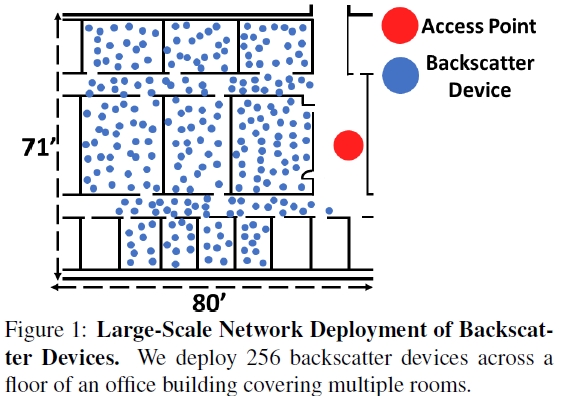
The paper presents the first wireless protocol that scales to hundreds of concurrent transmissions from backscatter devices. The key innovation is a distributed coding mechanism that works below the noise floor, operates on backscatter devices and can decode all the concurrent transmissions at the receiver using a single FFT operation. The design addresses practical issues such as timing and frequency synchronization as well as the near-far problem. The authors deploy their design using a testbed of backscatter hardware and show that our protocol scales to concurrent transmissions from 256 devices using a bandwidth of only 500 kHz. Their results show throughput and latency improvements of 14–62x and 15–67x over existing approaches and 1–2 orders of magnitude higher transmission concurrency.
Main content
The last few years have seen rapid innovations in low-power backscatter communication, culminating in long range and reliable backscatter systems. While these long range backscatter systems are not designed to scale with the number of devices-all these prior designs are evaluated in a network of 1–2 devices.
The goal in this paper is to design a network protocol that enables these low-power backscatter networks to support hundreds to thousands of concurrent transmissions. This is challenging because the resulting design must operate reliably with weak backscatter signals that can be close to or below the noise floor. To this end, we present NetScatter, the first wireless protocol that can scale to hundreds and thousands of concurrent transmissions from backscatter devices. Our design enables concurrent transmissions from 256 devices over a bandwidth of 500 kHz. Consequently, it can support transmissions from a thousand concurrent backscatter devices using a total bandwidth of only 2 MHz.
Our key innovation is a distributed coding mechanism that satisfies four key constraints: i) it enables hundreds of devices to concurrently transmit on the same frequency band, ii) it can operate below the noise floor while achieving reasonable bitrates, iii) its coding operation can be performed by low-power backscatter devices, and iv) it can decode all the transmissions at the receiver using a single FFT operation, thus minimizing the receiver complexity.
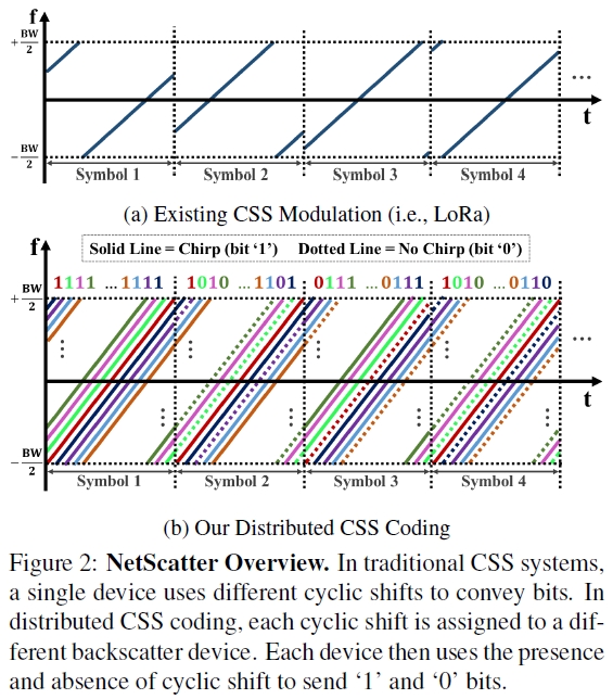
We introduce distributed chirp spread spectrum coding, which uses a combination of chirp spread spectrum (CSS) modulation and ON-OFF keying.
In existing CSS systems, the AP transmits a continuous wave signal which each device backscatters and encodes bits using different cyclic shifts of a chirp signal. In contrast, in our distributed CSS coding, we assign a different cyclic shift of the chirp to each of the concurrent devices. Each device uses ON-OFF keying over these cyclic shifted chirps to convey bits,i.e., the presence and absence of the corresponding cyclic shifted chirp correspond to a ‘1’ and ‘0’ bit respectively, as shown in Fig. 2.
Challenging
Near-far problem
A fundamental problem with enabling concurrent transmissions is that signals from a nearby backscatter device can overpower a farther concurrent device.
Solve : First, we present a power-aware cyclic shift allocation technique, where lower SNR devices use much different cyclic shifts than higher SNR devices. The backscatter devices that have an SNR difference of up to 35 dB to be concurrently decoded.
Second, to account for channel variations over time, we develop a zero-overhead power adaptation algorithm where backscatter devices use reciprocity to estimate their SNR at the AP, using the signal strength of the AP’s query message. The backscatter devices then adjust their transmission power to fall within the tolerable SNR difference. Since this calibration is done independently at each backscatter device using the AP’s query, it does not require additional communication overhead at the AP.
Timing synchronization
The above design requires all the devices to start transmitting at the same time so as to enable concurrent decoding. However, hardware variations and propagation delays of different devices can make it challenging for hundreds of devices to be tightly synchronized in time.
To avoid this coordination overhead, we leave gaps between cyclic shifts to ensure that concurrent devices can be decoded.
CSS Primer & Existing Approaches
Primer on Chirp Spread Spectrum
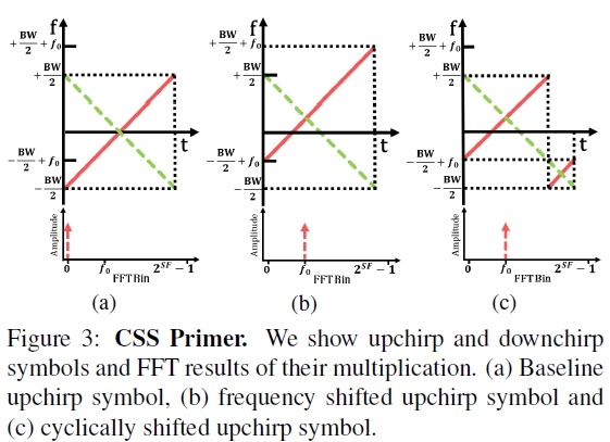
In CSS, data is modulated using linearly increasing frequency signals or upchirps. The receiver demodulates these symbols in a two step process. First, it de-spreads these upchirp symbols by multiplying them by a downchirp and it then performs an FFT on the de-spread signal. Since the slope of the downchirp is the inverse of the slope of the upchirp, multiplication results in a constant frequency signal, as shown in Fig. 3(a). Thus, taking an FFT on this will lead to a peak in an associated FFT bin. Changing the initial frequency of an upchirp will result in a change in the demodulated signal’s FFT bin peak index which corresponds to the initial change in frequency, as shown in Fig. 3(b). This property is used to convey information. When the sampling rate is equal to chirp bandwidth (BW), frequencies higher than BW/2 will alias down to -BW/2 as shown in Fig. 3(c). This means cyclically shifting in time is equivalent to changing the initial frequency and thus to conserve bandwidth, CSS uses cyclic shifts of the chirp in the time-domain instead of frequency shifts. This means that to modulate the data we just need to cyclically shift the baseline upchirp in time. Based on above explanations, CSS can be characterized by two parameters: chirp bandwidth/sampling rate and spreading factor(SF). This means increasing SF or decreasing BW decreases the bitrate. Further, the sensitivity of the system depends on the symbol chirp duration and increases with SF and decreases with BW.
Existing Collision Approaches
1.Using different spreading factors.
Use different spreading factors to each device, which increases the receiver complexity with the number of concurrent transmissions and decreases sensitivity. At the same time, if two chirp symbols transmitted concurrently with different BW and different SF, which result in the same chirp slope. There are only 19 different BW and SF pairs that could be used concurrently. Further, requiring receiver sensitivity better than -123 dBm and bitrates of at least 1 kbps limits these concurrent configurations to only 8, which does not support hundreds of concurrent devices on a 500 kHz band.
2.Choir
Radios have slight variations which result in timing and frequency offsets, which translate to fractional shifts in the FFT indexes. Choir uses these fractional shifts, with a resolution of one-tenth of an FFT bin, to map the bits to each transmitter. However, this approach does not scale to more than 5 to 10 concurrent devices.
NetScatter Design
Distributed CSS Coding
if we look at the FFT plots of Fig. 3, all the FFT bins except one bin are empty; however these empty bins could be utilized for orthogonal transmissions. Each device is assigned to a particular cyclic shifted upchirp symbol. It sends data by either sending the upchirp symbol or not sending it, i.e., by using ON-OFF keying of its assigned cyclic shifted chirp.
Receiver complexity
The received signal can be demodulated by despreading with a baseline downchirp multiplication and performing an FFT operation. Then, we can determine the presence and absence of a peak in each FFT bin and find if the corresponding backscatter device is sending ‘0’ or ‘1’. This means that the receiver complexity is nearly constant with the number of devices.
Throughput gain
There can be as many as 2^SF transmissions at each symbol period. Individual data rate is BW/2^SF,the aggregate network throughput is equal to BW. In comparison, LoRa have a throughput of BW*SF/2^SF. Thus, we can achieve a throughput gain of 2^SF/SF, which shows that the gain exponentially increases with the SF value used in the system.
NetScatter and CDMA
The distributed CSS coding can be thought of as code-division multiplexing mechanism that is low-power and where each of the 2^SF cyclic shifts is in an orthogonal set of codes in a CDMA system. These orthogonal codes are then assigned to 2^SF different backscatter devices which enables 2^SF concurrent transmissions.
Gain in the context of Shannon capacity
The systems that operate below the noise-floor, the network capacity scales linearly with the number of users. This linear increase stems from the fact that the N backscatter devices put in N times more power back to the AP than a single backscatter device.
Bandwidth aggregation
The bitrate achieved by each backscatter device in the distributed design is given by BW/2^SF and the number of concurrent devices is 2^SF. Thus, while we can increase the number of devices by increasing SF, it would decrease the bitrate of each device. Thus, to increase both the bitrate and the number of device we should increase the bandwidth, BW.
Addressing Practical Issues
Timing Mismatch
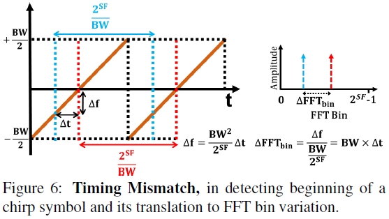
Now say that we demodulate the signal in these two timing durations, shown in blue and red, we will get different FFT peak locations.,as shown in Fig. 6.
In the design the access point sends a query message telling devices to transmit concurrently. The devices use this query to synchronize and respond concurrently.
There are multiple factors that can contribute to time delays introduced in practice.
- Hardware delay.
- Propagation delay and multipath.
Solution: Bandwidth-based cyclic-shift assignment.
About hardware delay variation over time, the solution to this problem is to put a few empty FFT bins adjacent to each FFT bin assigned to a device. That is, if FFT bin i is assigned to a device, the adjacent SKIP-1 FFT bins are empty and not assigned to any device. This can be done by using only every SKIP^th cyclic shift of the chirp. This ensures that the hardware delay does not result in interference between adjacent devices. For our implementation, we pick the same total bandwidth and chirp BW of 500 kHz and SF = 9 which supports around 1 kbps (976 bps) bitrate at each device while ensuring that the number of empty bins between devices, SKIP, is two.
Frequency Mismatch
The devices experience frequency offsets because of hardware variations in the crystals used in their oscillators. The change in frequency translates to FFT bin change of the demodulated device packet. This again, causes one device to be misinterpreted as other device. Since backscatter devices run at a few MHz frequencies, this frequency variation translates to less than one FFT bin for the bandwidths and spreading factors in this paper which makes it negligible for our backscatter network.
Near-Far Problem
Since the network are designed to work in below-noise conditions, it needs to address the near-far problem in the decoding process at the receiver. Specifically, to account for the residual timing and frequency offsets, a CSS receiver has to achieve a sub-FFT bin resolution. To do so without increasing the sampling rate, the receiver uses zero-padding which adds zeros at the end of the time domain samples of the single chirp. However, convolving with a sinc function introduces side lobes as shown in Fig. 8.
Solution:
- Coarse-grained power-aware cyclic shift assignment.
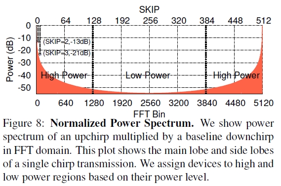
Fig. 8 suggests that we should assign adjacent FFT bins to devices that have a small SNR difference. we need to ensure that a lower SNR device has to correspond to FFT bins that are farther from the FFT bins corresponding to higher SNR devices. Specifically, we assign different cyclic shifts to different devices at association phase to ensure that the FFT bins corresponding to the lower-SNR devices are close to each other and are far from higher-SNR devices. To do this, the AP computes the signal strength of the incoming device in the association phase and assigns its cyclic shift based on its signal strength and also the strengths of the devices that are already in the network.
- Fine-grained self-aware power-adjustment.
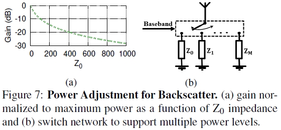
While the above assignment is determined at association, mobility in the environment and fading will change the SNR of each of the devices over time. To address this, each device adjusts its power over time using the signal strength of the query message from the AP, using three different levels. First, during association, we consider two cases for the associating device. If it sees a low received signal strength for the AP’s query packet, it sets its power gain to the maximum. Otherwise, it sets its gain to the middle level. The AP uses the resulting backscatter signal strengths during association to assign a corresponding cyclic shift. The backscatter devices use the signal strength at association as a baseline and either increase or decrease their power gains for the rest of the concurrent transmissions, i.e., if the signal strength for the AP’s query message increases(decreases), the backscatter devices decrease (increase) their power gain. One way to achieve this is to switch between extreme impedance values.
NetScatter Protocol & Receiver Details
The AP transmits an ASK modulated query message which is used to synchronize all the participating concurrent devices. This message conveys information about cyclic shift assignment which are based on the devices’ signal strength at the AP. Since the AP knows the duty-cycle of each device from the association phase, it can i) assign the cyclic shifts and ii) schedule the devices involved in concurrent transmissions.
Link-Layer Backscatter Packet Structure
Similar to LoRa, the device packet starts with upchirp and downchirp preambles. They are designed to serve two purposes: i) finding the start of the packet and ii) detecting the transmissions.
-
Finding the exact packet start. We use the downchirp in the preamble to find the start of the packet transmission.
-
Detecting and decoding each concurrent transmitter. We found the packet start, we need to find out which transmitters are in the network.
Network Association
All the devices transmit at the same time but the ones who want to enter the network transmit with the Nassoc association cyclic shifts. To address the near-far problem, we reserve two cyclic shifts, one in high-SNR and the other one in the low-SNR cyclic shift regions. The incoming device would choose which association region to transmit based on the signal strength of the AP’s query message, calculated using the envelope detector. However to account for the hardware delay variations, as before, we skip two cyclic shifts to ensure that the association packets from the devices can be decoded and will not interfere with communication cyclic shifts. Finally, to support scenarios where more than one device want to associate at the same time, one can use Aloha protocol with binary exponential back-off in the association process.
AP Query Message

Fig. 11 shows the ASK-modulated query message that the AP sends.
Network Protocol
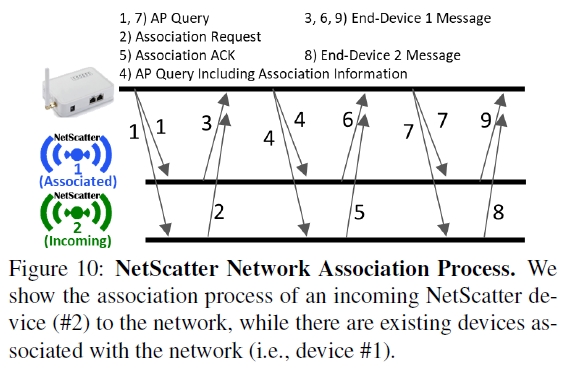
Fig. 10 summarizes our network protocol. First the AP broadcasts its query. Device 1, which is already associated to the network receives the query and sends its data using its assigned cyclic shift after performing any necessary power control. Concurrently, device 2 sends a Association Request using one of the Nassoc cyclic shifts. The AP receives these two messages and broadcast another query which includes association information for device 2. Upon receiving this query, Device 1 continues to send its data, however, device 2 extract cyclic shift assignment from the query and then transmits Association ACK to the AP in the assigned cyclic shift. If AP receives Association ACK, it adds device 2 to associated devices. Otherwise, it will repeat the association information in the following queries. After association, each device uses its assigned cyclic shift for sending data.
Hardware Implementation
Implementation Using Discrete Hardware Components.
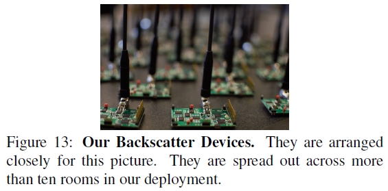
Our discrete hardware implementation shown in Fig. 13 consists of RF section and baseband section, both implemented on a four layers FR4 PCB. On RF receive side, we implemented envelope detector at 900 MHz and it has a sensitivity of -49 dBm to receive downlink query messages from AP. RF transmit side consists of five ADG904 switches cascaded in three levels to build an impedance switch network for backscatter, power gain control and also switching between transmit and receive modes. Our backscatter device uses a 2 dBi whip antenna to transmit packets and receive query messages in the 900 MHz ISM band. The baseband side is implemented using an IGLOO nano AGLN250 FPGA and an MSP430FR5969. We generate CSS packets on the FPGA and output real and imaginary components of the square wave signal to the backscatter switch network. The envelope detector is controlled by the MCU. Downlink receiver algorithm is implemented on MCU. To be resilient to self-interference caused by the AP’s single-tone, the baseband at the backscatter device shifts the AP’s signal by 3 MHz. Note that the discrete implementation is for prototyping and proof-of-concept; an ASIC is typically required to achieve the orders of magnitude power benefits of backscatter communication. We use a battery to power each backscatter device for our evaluations.
Access Point Implementation.
We implement the access point on the X-300 USRP software-defined radio platform by Ettus Research. We use a mono-static radar configuration with two co-located antennas separated by 3 feet. The transmit antenna is connected to a UBX-40 daughterboard, which transmits the query message and the single-tone signal. The USRP output power is set at 0 dBm and we use an RF5110 RF power amplifier to amplify the transmit signal to 30 dBm. The receiver antenna is connected to another UBX-40 daughterboard, which down-converts the NetScatter packets to baseband signal and samples them at 4 Msps.
Conclusion
The authors present a new wireless protocol for backscatter networks that scales to hundreds of concurrent transmissions. To this end, the authors introduce, distributed chirp spread spectrum coding, which uses a combination of chirp spread spectrum (CSS) modulation and ON-OFF keying. Further, the authors address practical issues including near-far problem and timing and frequency synchronization. Finally, the authors deploy our system in an indoor environment with 256 concurrent devices to demonstrate its throughput and latency performance.
Paper
Paper 👉Paper Pages
Video 👉Video
Blog 👉Blog
Lab 👉Lab