A Multi-Channel Software Decoder for the LoRa Modulation Scheme
Abstract
LoRa is a recently introduced modulation scheme specifically designed for Low-Power Wide-Area Networks. In this paper, we provide the first detailed and complete description of the LoRa PHY layer, and present a novel methodology for detecting and decoding LoRa frames using Software Defined Radios. Our proposed decoding approach can efficiently decode multiple channels simultaneously in software due to an invariance towards the signal frequency. Hence, our approach also removes the need for correcting frequency offset errors imparted by the transmitter or receiver. We have evaluated our decoding technique in a lab setup using three Software Defined Radios (USRP B210, HackRF, and RTL-SDR) and three commercial off-the-shelf hardware LoRa transceivers (Microchip RN2483, HopeRF RFM96, and Semtech SX1272). We show that our decoder is fully compatible with all configurations of the RN2483 and SX1272, achieving an overall packet error rate of 0 for a signal-to-noise ratio of 20 dB. The source code of the decoder and datasets used in the evaluation are made available publicly.
Main content
In coming years, the industry is expected to show an increased interest in Low-Power Wide-Area Networks (LPWANs) and their applications, such as smart metering, location tracking, Wireless Sensor Networks (WSNs), smart transportation systems and health monitoring (i-SCOOP, 2017). The authors proposed algorithms for the detection, synchronization, and decoding of raw PHY-layer LoRa frames using Software Defined Radios (SDRs). These algorithms include a novel decoding approach and a novel clock drift correction approach for LoRa, both implemented in a complete and open-source software LoRa decoder using the GNU Radio framework. The decoder is capable of decoding multiple channels simultaneously in real time regardless of the frame’s network identifier, similar to the capabilities of “monitoring mode” devices in context of 802.11 (Wi-Fi).
LoRa PHY LAYER
In order to correctly decode LoRa-modulated data, a receiver must sequentially perform seven operations on the PHY layer, namely detection, synchronization,demodulation, deinterleaving, dewhitening, decoding, and packet construction.
Modulation
A standard, unmodulated linear chirp is called a “base chirp”, and can be mathematically described in function of the time t as follows
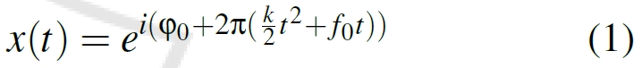
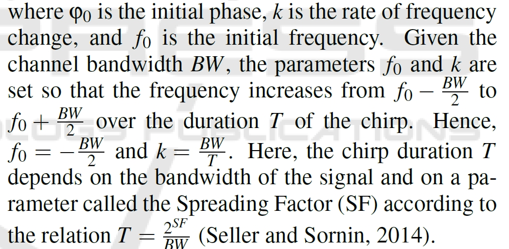
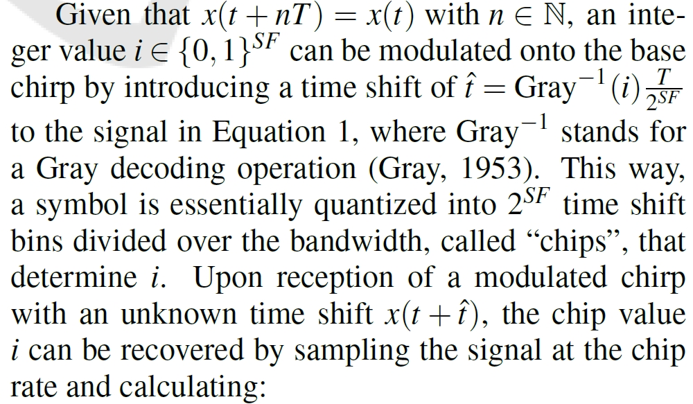

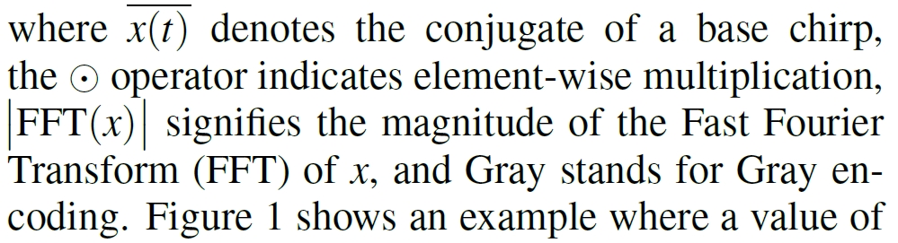
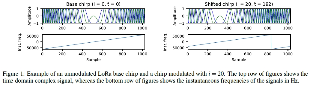
Figure 1 shows an example where a value of i = 20 is modulated onto the base chirp, shifting it by 192 samples.
Interleaving
In order to limit the impact of bursty noise to a single bit error per symbol, multiple chip values are stacked together such that a bit matrix{0,1}^SF×(4+CR) is obtained. Here, the Coding Rate (CR) or equivalently, the number of parity bits, can range from 1 to 4. For example, when using SF = 7 and CR = 4, we obtain a matrix {0,1}7×8 as shown in Figure 2.
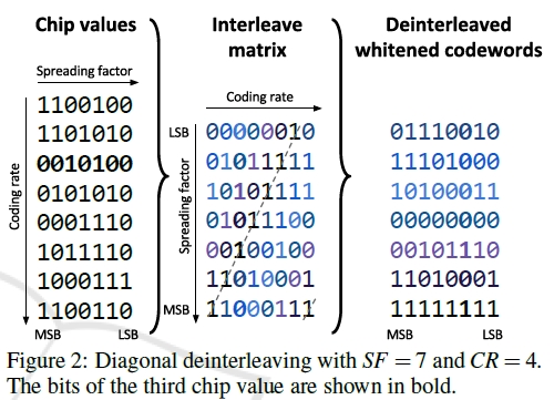
The LoRa specification also defines a “reduced rate” mode, in which the top two rows of the interleaving matrix are discarded. Consequently, the dimensions of the matrix become {0,1}^(SF−2)×(4+CR), yielding two codewords less after deinterleaving. The discarded rows correspond to the LSBs of the chip values, which are more prone to errors because they correspond to narrower frequency bins in the FFT spectrum. Therefore, in reduced rate mode, a decreased data rate is traded for an increased robustness to noise. The PHY layer header of LoRa frames is always transmitted in reduced rate mode, whereas the payload bytes are only transmitted in reduced rate mode when SF 11 or SF 12 is used
Coding
After deinterleaving, a number of codewords of size 4+CR are obtained by the receiver. The codewords of the frame payload are “whitened” in order to keep the data Direct Current (DC)-free. Here, whitening is defined as an operation where the data is XOR-ed with a 9-bit Linear Feedback Shift Register (LFSR) after synchronization.
The authors reverse engineered the coding scheme and discovered that a modified version of 4/(4+CR) Hamming coding is utilized in practice. Hence, each codeword results in 4 data bits when decoded, which are subsequently parsed according to the LoRa frame structure.
Frame Structure
On the PHY layer, LoRa defines a frame structure with the following sequentially transmitted fields:
-
Preamble: A variable-sized sequence of base chirps that is used for time and frequency synchronization.
-
Frame synchronization symbols: Two modulated chirps whose value can be used as a network identifier. A hardware LoRa transceiver will drop frames containing synchronization symbols that do not match a preconfigured value.
-
Frequency synchronization symbols: Two conjugate base chirps followed by a conjugate chirp with duration T/4 , which can both be used for fine frequency synchronization.
-
Header (optional): Field containing the payload length, used data rate, a bit indicating the presence of a payload Cyclic Redundancy Check (CRC), and 1-byte header checksum. A CR of 4 is always used in combination with reduced rate mode for the header2 (Seller and Sornin, 2014). The header can be explicitly transmitted (explicit mode) or left out of the frame (implicit mode). In the latter case, the transmitter and receiver must configure the coding rate and CRC presence bit beforehand.
-
Payload: Variable-length field containing the transmitted Medium Access Control (MAC) layer data and a 2-byte CRC of this data.
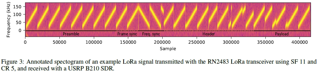
Figure 3 shows an example LoRa signal and its frame structure.
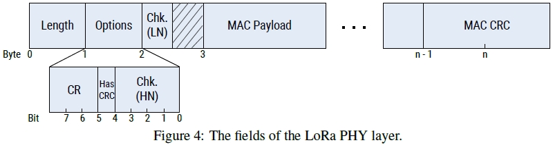
The authors have experimentally determined that when transmitting data using a Microchip RN2483 LoRa transceiver, the left-to-right order of the PHY header is as follows: a single payload Length byte, followed by a nibble for the CR andMAC CRC presence, the High Nibble (HN) of the header checksum, and finally the Low Nibble (LN) of the header checksum. An overview of these fields is given in Figure 4.
SOFTWARE DEMODULATOR
An overview of the decoder components is given in Figure5.
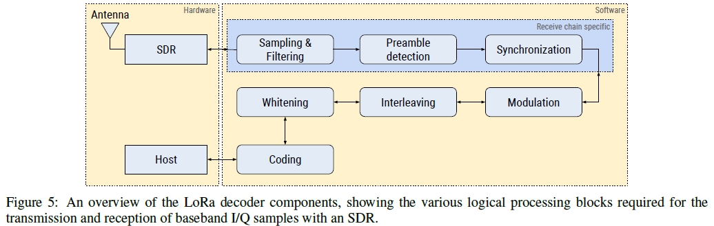
Detection and Synchronization
As a first step in the demodulation process, the receiver must detect the LoRa preamble. To this end, the authors exploit the repeating property of the preamble by using the Schmidl-Cox algorithm.
| M(d)= | P(d) | ^2/R(d)^2 |
The timing metric M(d) essentially calculates a normalized autocorrelation of length L over two symbols, which will be maximal when two consecutive symbols are encountered in the signal. To efficiently compute Equation in software, it can use Single Instruction, Multiple Data (SIMD) instructions provided by Vector Optimized Library of Kernels (VOLK).
Demodulation
The FFT-based demodulation approach specified in (Seller and Sornin, 2014) is sensitive to frequency offset errors, which cause the magnitudes of the FFT (and thus the chip values) to shift. Therefore, an accurate frequency synchronization is required. Furthermore, this synchronization must be applied for each LoRa channel separately in order to fulfill our requirement of multi-channel decoding.
The authors’ technique removes the need for frequency corrections and allows to decode LoRa frames in real time on all channels and without additional processing overhead, but at the cost of a reduced robustness compared to the FFT approach
Decoding
In the decoding stage, the chip values are deinterleaved to form codewords of 4+CR bits. The first 8 codewords of a frame can be directly decoded to form the PHY-layer header. On the other hand, we found that the payload symbols must be dewhitened first.
Clock Drift Correction
To correct for the clock drift, the authors propose a blind estimation technique5 that exploits oversampling of the transmitted signal at a rate of N.
Conclusion
In this paper, we have provided an in-depth examination of the LoRa PHY layer, and demonstrated our open source LoRa software decoder, which is implemented using the GNU Radio framework. Our decoder can be used in real time with inexpensive SDRs such as the RTL-SDR, and is able to interoperate with existing LoRa transceivers. A set of frequency invariant techniques for the detection, demodulation, and clock drift correction of LoRa frames were introduced, which result in the capability to decode multiple channels simultaneously in real time, at the cost of an increased sensitivity to noise compared to COTS LoRa radios. Our evaluation shows that a SNR of at least 20 dB is required for the PER to approach 0.
Paper
Paper 👉Paper Pages
Video 👉Video
Blog 👉Blog
Lab 👉Lab