Challenge:RFID Hacking for Fun and Profit Batteryless Sensors
Main Content
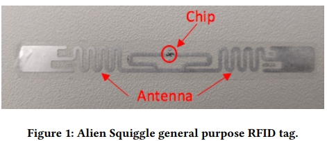
This paper discusses how to use simple modifications of commodity RFID tags to turn them into batteryless, wireless, low-cost sensors. By suitably integrating a phototransistor or a thermistor into a commodity RFID tag, which can convert it into the light or temperature sensor.The author also propose and evaluate a new legacy-compatible tag reading protocol called Differential Minimum Response Threshold (DMRT) that is robust to the changes in the RF environment.
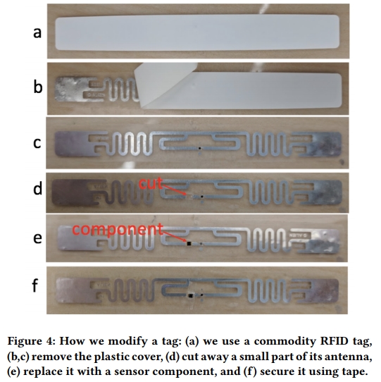
Figure 4 shows the steps to modify an RFID tag. First remove the plastic cover on the tag to expose the antenna, which is a thin metallic strip on a plastic base. Next, cut away a small part of its antenna. Finally, place a sensor such as a phototransistor or a thermistor to replace the cut part and secure it on the tag using the clear plastic tape.
CHALLENGES AND DISCUSSION
Improving the sensing accuracy
The resolution of DMRT in our implementation is 0.25 dBm, a limitation of our reader.To improve this resolution, one can design or use a reader which has finer granularity for changing transmission power. Second, we need to identify sensors that consistently detune RFID antennas when exposed to changes in the environment.
Improving the sensing range
An unmodified tag has a range of ∼7-11 m, but modified tags have a range that is only about 4 m. To improve the tag’s reading range, the sensor should not significantly detune the antenna gain and sensitivity. One way to achieve this is by using a rigorous tag antenna model to model cutting and placing a sensor on the tag antenna. Alternatively, one can design a compensation scheme to ensure the impedance match between the sensor and the tag antenna.
Real-time DMRT estimation
In our current implementation, it takes ∼0.1-7.2 s to estimate DMRT, since each transmission power can be changed only every 0.1 s when sweeping power. This limitation of the reader hardware makes it difficult to track a fast-moving gesture. To solve this issue, the challenge is to design a reader that can sweep the transmission power more quickly.
Removing the parasitic capacitance.
Given the 900 MHz RFID signal, even a parasitic capacitance of a few pF can result in the sensor’s impedance exceeding the target range or potentially short circuit the sensor. To solve this problem, we place an additional small capacitor in series with the sensor to limit its impedance. However, this can reduce the sensor’s accuracy. Alternatively, it is possible to cancel the parasitic capacitance by putting an appropriate inductor in parallel with the sensor. This inductor, of the order of a few nH, must be chosen with care.
Paper and Video
Paper 👉Paper Pages
Video 👉Video
Products 👉Products